14 September 2010
Ferramentas de corte e modelagem para construção modular e dispositivos para usinagem e montagem. Nunca antes as chapas metálicas foram tão amplamente utilizadas como atualmente. Isso foi possível graças ao aprimoramento das técnicas de processamento e aos novos materiais. Uma parte integrante da cadeia perfeita do processo de chapas metálicas também é, obviamente, o sistema CAD/CAM correto. Na Pockauer Werkzeugbau Oertel GmbH (PWO), o sistema escolhido foi o TopSolid da Missler Software.
CRESCIMENTO SÓLIDO COM CONHECIMENTO DE CAD/CAM
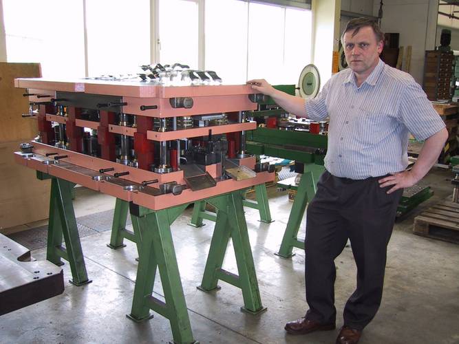
"90% da atividade da PWO está relacionada ao setor automobilístico", afirma o chefe da empresa, Matthias Oertel. A empresa produz ferramentas de corte e modelagem com até 800 mm de comprimento (ferramentas de matriz progressiva) e ferramentas de acompanhamento com até 3.000 mm de comprimento para construção modular e dispositivos para usinagem e montagem. Entre outras coisas, as ferramentas são usadas para a fabricação de alavancas, dobradiças e acessórios para portas e persianas, além de peças para ajustadores de assentos, componentes de engrenagens e assim por diante.
"Ao abranger a cadeia de processos de ponta a ponta, tudo sob o mesmo teto, podemos atender aos desejos individuais de nossos clientes a uma taxa altamente econômica", continua o Sr. Oertel. A cadeia de processos é apoiada por um sistema CAD/CAM integrado, desde o momento em que os dados do cliente são recebidos até o pós-processamento dos programas NC. A PWO optou pelo TopSolid do fornecedor francês Missler Software em 1996, com o revendedor TopSolid West instalando-o e fornecendo o suporte técnico.
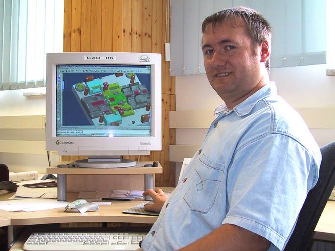
Descrever a PWO como um usuário avançado do TopSolid não seria exagero. Quase todas as possibilidades do software são exploradas, ocupando doze estações de trabalho no total. A cadeia de processos CAD/CAM entra em ação quando a geometria é fornecida. O TopSolid tem uma série de interfaces que permitem que as geometrias sejam importadas ou exportadas para outros sistemas. Essas interfaces incluem Catia®, Pro/Engineer®, Solidedge® e Solidworks® como interfaces nativas e IGES, STEP, DWG, etc., como interfaces padrão. De acordo com o Sr. Oertel, essas interfaces "foram significativamente aprimoradas nos últimos anos e hoje funcionam sem problemas".
A próxima etapa é a geração de um layout de tira (colocação da chapa metálica desenrolada na tira de estampagem). As funcionalidades de chapa metálica do pacote CAD/CAM ajudam nessa tarefa. Depois que o layout da tira é aprovado, a construção da ferramenta de fato pode começar. As primeiras a serem projetadas são as peças ativas (ou seja, aquelas que estão ativamente envolvidas no processo de corte, dobra e remodelagem), seguidas pelas placas, colunas, capacidades de expansão etc.
A PWO constrói tudo em 3D - até a peça mais simples - para adquirir um modelo virtual completo que serve continuamente como referência para todos os ciclos de trabalho progressivos. As ferramentas são construídas de forma modular, com o sistema permitindo, assim, a criação de uma estrutura clara de componentes.
Os fabricantes de ferramentas fazem excelente uso dos parâmetros do sistema. Nas palavras do Sr. Oertel: "Os paramétricos podem ser de grande utilidade se o fabricante de ferramentas for capaz de usá-los com habilidade". Ele dá como exemplo a alteração do rebaixo de uma ferramenta para compensar o retorno elástico da chapa metálica. "Se, durante a execução de uma ferramenta, percebermos que o retorno elástico não é o esperado, teremos que alterar o ângulo do rebaixo. Teoricamente, isso significa modificar todas as superfícies envolvidas e envolve um período de tempo de dois a três dias. No entanto, se os parâmetros forem configurados corretamente, o mesmo trabalho pode ser feito em dez minutos, bastando inserir alguns parâmetros!"
A PWO constrói suas ferramentas, na medida do possível, usando componentes padrão do setor, mas precisa, além disso, de um amplo espectro de peças padrão proprietárias. Para isso, foi criada uma biblioteca proprietária abrangente, que, obviamente, é mantida atualizada e que se paga por si mesma devido ao seu uso frequente.
Quando a construção 3D é concluída, os desenhistas técnicos produzem um desenho 2D derivado, que ainda é necessário para os clientes, sua própria oficina e, quando necessário, para os subcontratados. Paralelamente a isso, começa a programação NC. Como, nesse sistema, o CAD e o CAM são integrados em um único núcleo, não há perda de dados nem inconsistências, o que ajuda a minimizar os custos de programação NC. O programador NC usa o sistema para gerar caminhos NC, desbaste, acabamento e fresamento de região residual e para implementar uma simulação NC. Isso significa que a oficina obtém programas NC finalizados, nos quais não há mais necessidade de ajustes e otimizações de última hora e apressados.
Na PWO, no entanto, apenas as peças 3D são programadas para fresamento de 3 eixos com o TopSolid'Cam. Todas as peças 2D são fresadas e programadas na oficina. Até o momento, essa tem sido considerada a maneira mais rápida de proceder. Tudo o que resta é o pós-processamento das peças 3D, e então você terá feito sua jornada "até o fim da ideia", como sugere a Missler Software em um de seus folhetos.
Ao longo dessa cadeia de processos, Matthias Oertel e seus colegas valorizam acima de tudo: "a alta eficiência e o fácil manuseio do sistema. Se pudéssemos escolher novamente, esse ainda é o sistema que escolheríamos".
Precisa de mais informações
PERGUNTA SOBRE NOSSO
PRODUTOS OU SOLUÇÕES?
Encontre o ponto de vendas mais próximo Contate-nos Obter uma cotação